
Self Balancing PID Robot

Over the summer, I wanted to improve my skills with control systems, microcontrollers, telemetry and sensor data. This culminated in a PID balancing robot, which will be detailed in this post. Some preview images are included below.
I began by ordering motors with encoders and drivers, which I had used for a prior project, to ensure they would not be challenging. Next, I chose to use an ESP 32 to gain experience with a microcontroller that could use Wifi and Bluetooth to transmit information. I also used a step-down voltage converter from 12V to 5V, as I needed two voltages: one for the sensors and microcontroller and one for the motor. Finally, I purchased an MPU 6050 gyroscope and accelerometer unit to measure the angle at which the system tilted.
At this stage, three design challenges had become clear: the housing design, the sensor filtering and telemetry output, and the PID controller.
The housing design underwent several iterations, starting with a two-floor setup: the microcontroller on the top floor and the battery, motors, voltage converter, and gyroscope on the lower floor. The initial iterations of this were large 3D-printed pieces that were prone to failure and were swapped for smaller pieces that were screwed together. In addition to this, the motor brackets were integrated into the system to eliminate the issues caused by the separate metal bracket shaking or loosening over time. A clip was also designed for the step-down voltage converter, as it had no mounting holes. The remaining circuit boards could be attached to the robot via brass stand-offs. Lastly, a switch was added to turn the robot off without unplugging the batteries, which was a consistent issue with other battery-based projects I had seen.
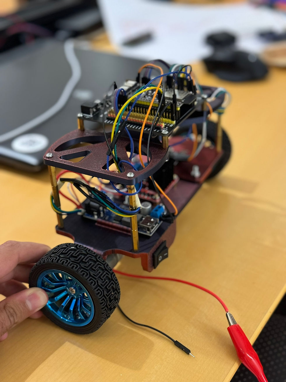
I then wired the project together. The wiring was fairly simple, consisting of 12V from the power supply to the switch to the motor driver and the voltage converter. The motor driver was connected to the power wires of each motor. The voltage converter was connected to the ESP-32, powering it with a steady 5V. The ESP-32 powered the encoders, took in the encoder data wires, and did the same for the gyroscope, but with 3.3V.
With the physical housing complete, I began to work on the robot's programming. This began by making a Kalman filter for the gyroscope. I set up the ESP-32 to use the Arduino IDE, wrote up a simple Kalman filter for the gyroscope, and tested it, and at first glance, it seemed to work quite well.
I now designed a simple PID controller to control the robot, adjusting the minimum speed to the minimum required speed to move the system, and I tuned my gains based on simple observation. This process seemed to bear no results, so I turned to a mentor for advice. He advised me to construct a telemetry output that I could view to diagnose any issues with my controller. I obliged and altered my code to output a JSON file to Matlab, which would then turn all these values into a table I could read. By doing this, I saw that my gyroscope was consistently 5 degrees off, so I adjusted my Kalman filter and added a manual offset, which instantly improved my results. Finally, after working on tuning my gains, I arrived at a robot that could balance well. This robot is in the video below.


That puppy is Balancing all right🤠