
Cargo Balancing Motion Control and Analysis Project

Updated: Aug 29, 2024
In this post, I will outline a project I undertook to improve my motion control and analysis skills. This project was twofold in its aims. The first aim was to design a vehicle capable of transporting an unaffixed bar 10ft. The second was to reliably control a vehicle's speed, direction, and position by using a pre-calculated velocity profile. This project began as an individual pursuit, where I designed my own take on this vehicle, complete with its velocity profile and simulation. The vehicle in question would be comprised of a 3D printed body, four wheels, and a gear power transmission system controlled by a motor with an encoder, driver, and an Arduino Uno. This design and simulation video are shown below.
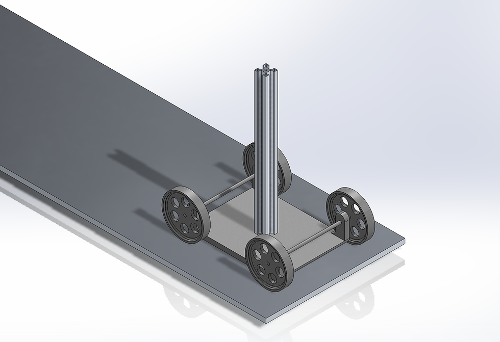
After this, three other students and I formed a team to best accomplish these aims. We combined and focused on our initial ideas and created a final design. This final design would be 3D printed out of silk PLA to adhere well and have a smooth finish for the parts of the assembly that would rub together. In addition to this, our final design incorporated rubber finishes on the wheels to increase their grip on the test track. Moreover, the vehicle is very low to the ground to increase its stability by lowering its center of gravity. Furthermore, the wheel diameter is very large, making the ride even more stable. This design is shown below.
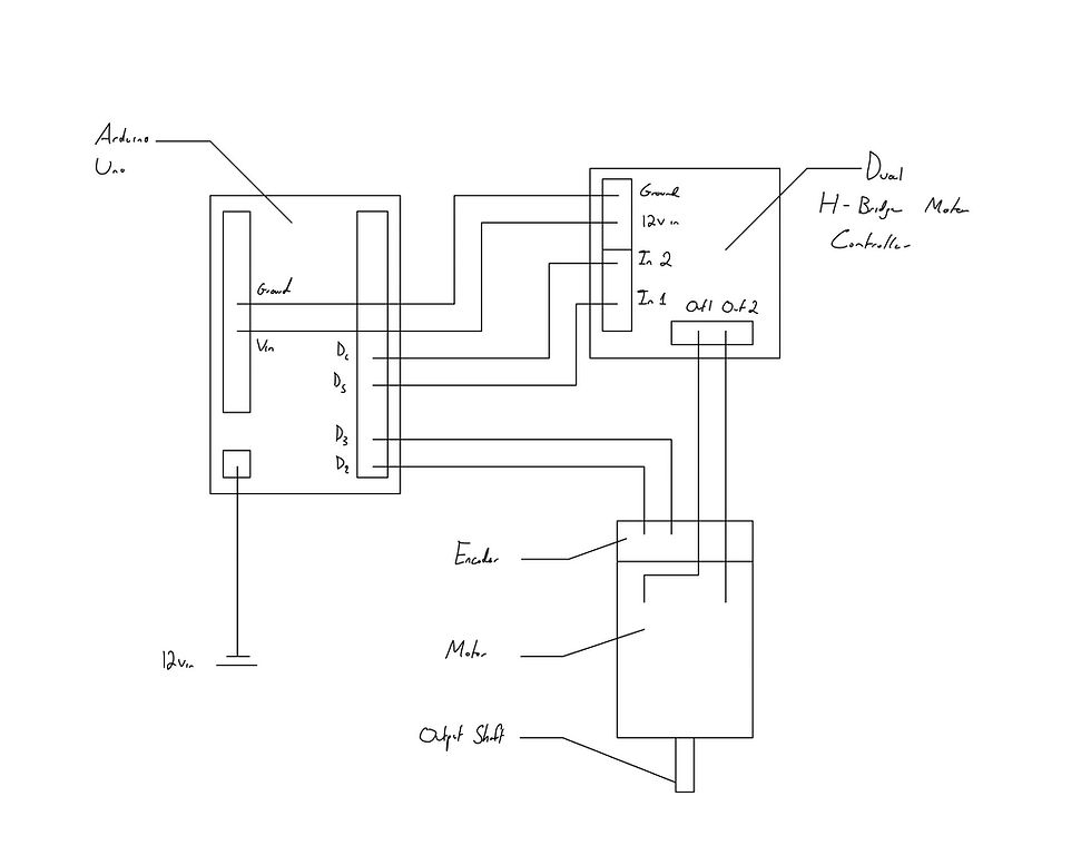
We then split the remaining tasks between ourselves to organize and streamline the production of this project. I was tasked with creating a velocity profile, wiring the circuit, and implementing the accompanying Arduino code to control a motor that is attached to the designed vehicle. I chose to use a trapezoidal velocity profile so that the calculation of the displacement and creation of the control code would be simple, and this was eventually integrated into the code. Using the physics of the bar, finding its maximum acceleration, and checking with our simulation, I found that the car would be able to go 10 feet with a maximum acceleration of 2rpm/s with our final design. From there, I wrote the Arduino code to control the vehicle and checked its details with my other team members to ensure that it was suitable for the task at hand. Lastly, I wired the circuit using an Arduino Uno, an H-bridge motor driver, and a combination motor encoder. The basic circuit schematic is shown below.
Circuit Schematic:
Finally, we assembled and tested the vehicle. It could go almost precisely 10 feet in just under 10 seconds. This was a success in our eyes, as the project accomplished the two significant aims we had set out to fulfil. Some improvements could be made to the code and the assembly, such as gears that meshed smoother and a rougher surface for the bar to rest on so that a larger acceleration could be used. A video of the final design is accessible via this link: https://youtube.com/shorts/xrfKGpGPk7Y
Below are also some assorted images of the project.


Comments