
Gasket Design Project

Updated: Sep 23, 2023
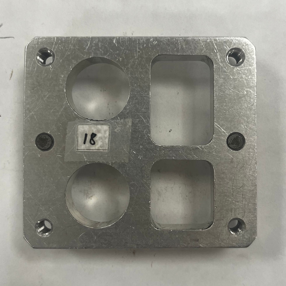
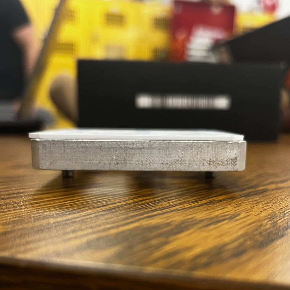
During the fall semester of my sophomore year, as a part of a course called Electromechanical Design (ME360), I was tasked with designing a gasket based on an existing metal part. The part in question was photographed and is displayed below.
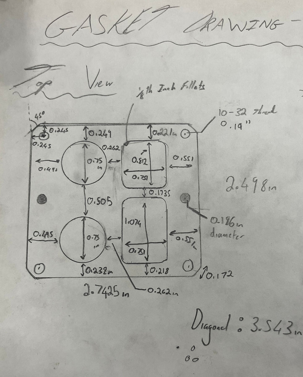
This project was done in stages, the first being the measurement and drawing of said part. The measurement was done using callipers, and these measurements were noted down on a sketch for later reference when designing the gasket in CAD. This sketch is displayed below.
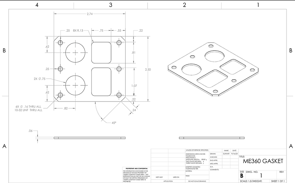
Next, I designed the gasket to the specifications obtained above. This was done relatively easily in Solidworks since the gasket required nothing beyond simple geometry, fillets and chamfers. Screenshots of both the finished part and the resulting drawing are below.
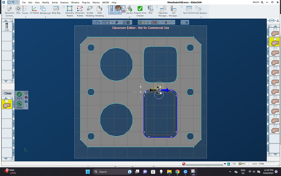
With the CAD model now finished, I imported the file into GibbsCAM. I first inputted the settings of the CNC Machine of my university's workshop. I then inputted the order of holes and slots to be cut, ensuring that everything was correctly inputted through the operation simulator function of the software. A screenshot of the GibbsCAM model is displayed below.
I then processed my GibbsCAM model into G-Code and uploaded it onto BU's Haas brand CNC machine. Next, I secured a piece of PVC to the bed of this machine using double-sided tape, checked with the staff that I had done everything correctly, and then pressed the start button on the machine. The design of the gasket was then carved onto the PVC, and once the machine had finished its work, I removed the physical prototype and deburred its edges. The resulting gasket is displayed below.
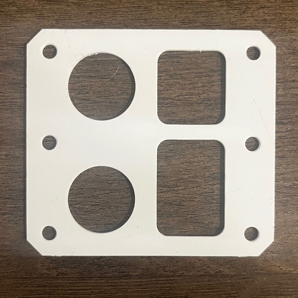
Finally, I tested the gasket against the metal block it was derived from. Unfortunately, there was one critical failure in the gasket, which was that the mounting holes were too small. There was also one lesser failure, which was that both the chamfers and horizontal edge were slightly too short in comparison to the block, and this meant that the part overall was slightly too small. Two images demonstrating this are below.
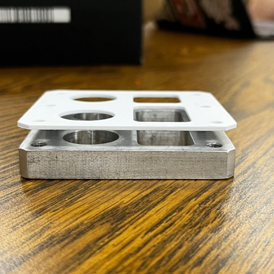
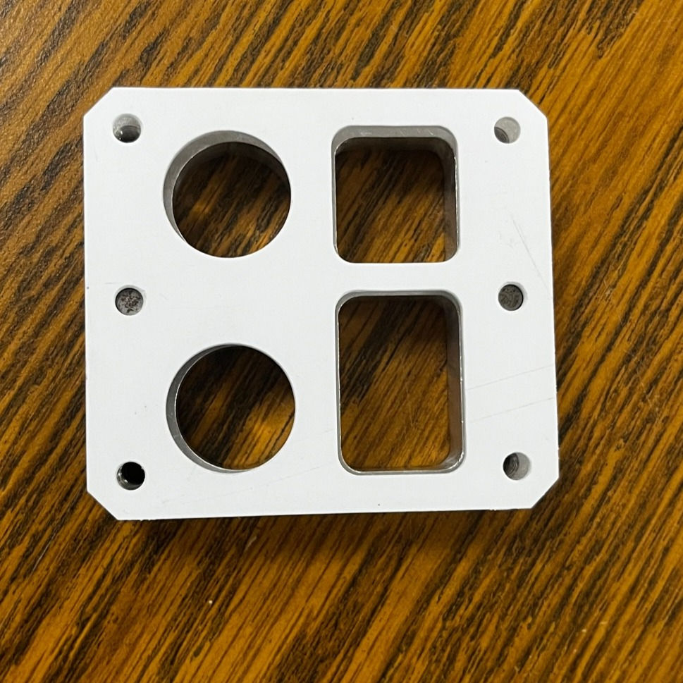
However, beyond this, the gasket was machined to specification, as the holes were all the right size with the right radius for fillets, as well as the actual shapes, were in the right position relative to one another. This is demonstrated by the images below, which place the gasket on the other side of the metal block in order to test the fit of the part on the machine without interacting with the mounting holes.
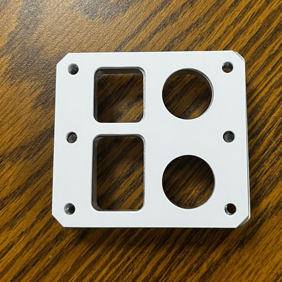
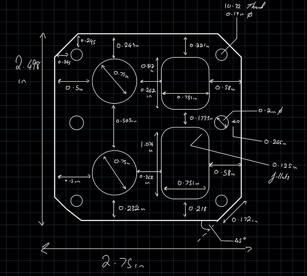
Therefore, to make this part viable for usage and potential production, I would need to re-measure the edge length and mounting pole diameter and correct this in the Solidworks CAD model, as well as produce a new drawing of said part to ensure that the measurements obtained match those used in the model. I would then machine this and check the fit once more, ensuring that everything fits together smoothly and properly onto the metal block. An updated drawing of the gasket is below.


Comments